
Landscape Architecture Plan Graphics: A Practical Guide

You've opened a garden designer's presentation and seen the garden you want: a carefully framed terrace, mature planting, a pool disappearing into the planting, perhaps a garden room beyond. Then the planning pack arrives, full of thin lines, abbreviations, dimensions and symbols. The attractive image makes the proposal feel real. The technical drawing explains what can be approved and built.
Both are necessary, but they answer different questions. Architectural plan graphics translate an idea into evidence. They show a planning authority where boundaries sit, how levels change, which trees remain, what surfaces are proposed and how the site relates to neighbouring properties. They also give architects, engineers, contractors and gardeners a shared reference point.
Why Landscape Graphics Matter
A homeowner may first respond to a persuasive garden image: a framed terrace, a quiet garden room or an outdoor kitchen connected to the house. That visual communicates atmosphere quickly, helping someone judge proportion, material character and the relationship between indoor and outdoor rooms. It can show whether the proposal feels calm, generous or suitably private.
Planning authorities require evidence that can be checked. A planning drawing must be scaled, coordinated and legible, so another professional can test the proposal rather than merely admire it. UK practice generally relies on scaled site, block and layout drawings, including location plans, site plans, floor plans, elevations and sections. Together, they establish boundaries, access, trees, open space, hard surfaces and the relationship between proposed works and surrounding buildings, as set out in UK plan and drawing standards.
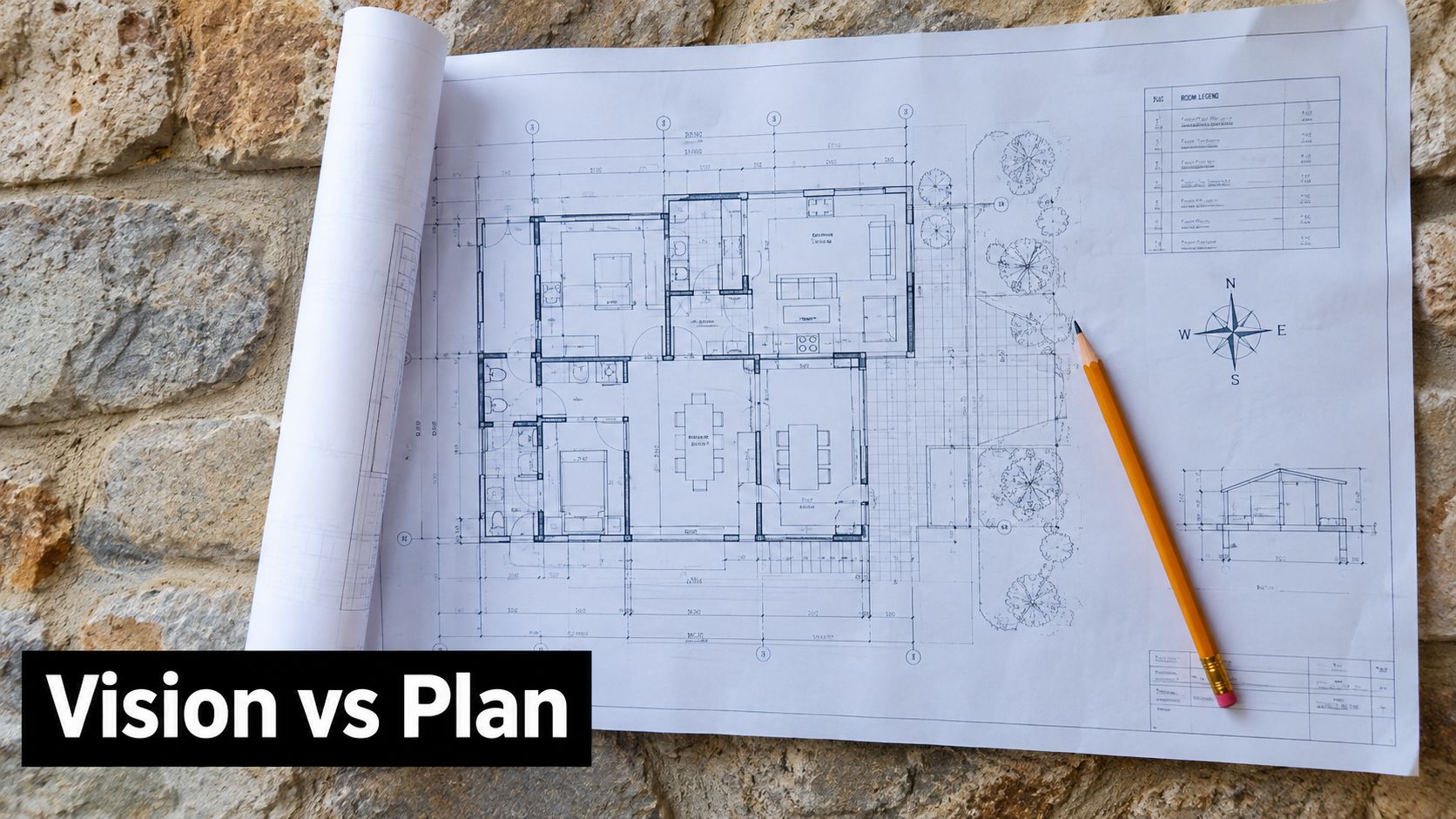
The drawing is part of the permission
For a constrained property in Wimbledon Village, a polished concept and an authoritative plan perform different jobs. A conservation officer may need to assess how a new terrace affects a historic boundary. A planning officer may need to check whether a raised platform changes overlooking. A contractor needs finished levels, material interfaces and construction information.
Presentation quality supports understanding, but it doesn't replace technical evidence. Shadows, planting and atmospheric effects can make a proposal attractive, yet they cannot resolve an unclear boundary, missing level or uncertain interface. The graphic must make the scheme easier to assess and coordinate.
The landscape architecture design process works best when visual communication develops alongside design decisions. Early graphics establish the spatial idea. Later drawings record those decisions with enough precision for planning and construction.
Practical rule: if a feature affects access, levels, drainage, trees, boundaries or neighbouring amenity, show it in a drawing that can be measured and coordinated.
Those drawings also become part of the permission record and the project's longer history. Historic England's collections include architectural drawings, plans and reports, while the Landscape Institute's archival resource documents the work and papers of Sylvia Crowe, Michael Brown and Sir Geoffrey Jellicoe. Plan graphics therefore serve delivery and preserve evidence of design intent and environmental change for future reference.
Understanding Core Graphic Types
The most useful distinction is not between hand-drawn and digital work. It's between graphics that communicate an idea, drawings that define a proposal and visuals that help people understand its eventual appearance.
A concept diagram is intentionally selective. It might use arrows to show movement, shaded areas to identify garden rooms or a simple massing sketch to explain how planting screens a neighbouring view. It doesn't usually need the dimensional authority of a planning drawing. Its value lies in helping the team make decisions before detail becomes expensive to change.
A technical plan takes the next step. It sets out the site, proposed elements, dimensions, levels, materials, planting areas and interfaces. A planting plan can identify vegetation types, soil zones and ecological intentions, while a construction drawing can describe the edge of a paving detail, the profile of a retaining wall or the relationship between finished ground and a threshold.
Three graphics, three questions
Graphic type | Main question | Typical use |
|---|---|---|
Concept diagram | What is the design trying to achieve? | Early briefing and spatial testing |
Technical drawing | What exactly is proposed? | Planning, coordination and construction |
Visual overlay | How will the proposal sit within its context? | Client review and impact assessment |
A rendered overlay sits between the expressive and the technical. It may place proposed planting, paving or structures over a measured base drawing or photograph. Used carefully, it lets a client understand scale and context. Used carelessly, it can imply a level of certainty that the underlying design hasn't earned.
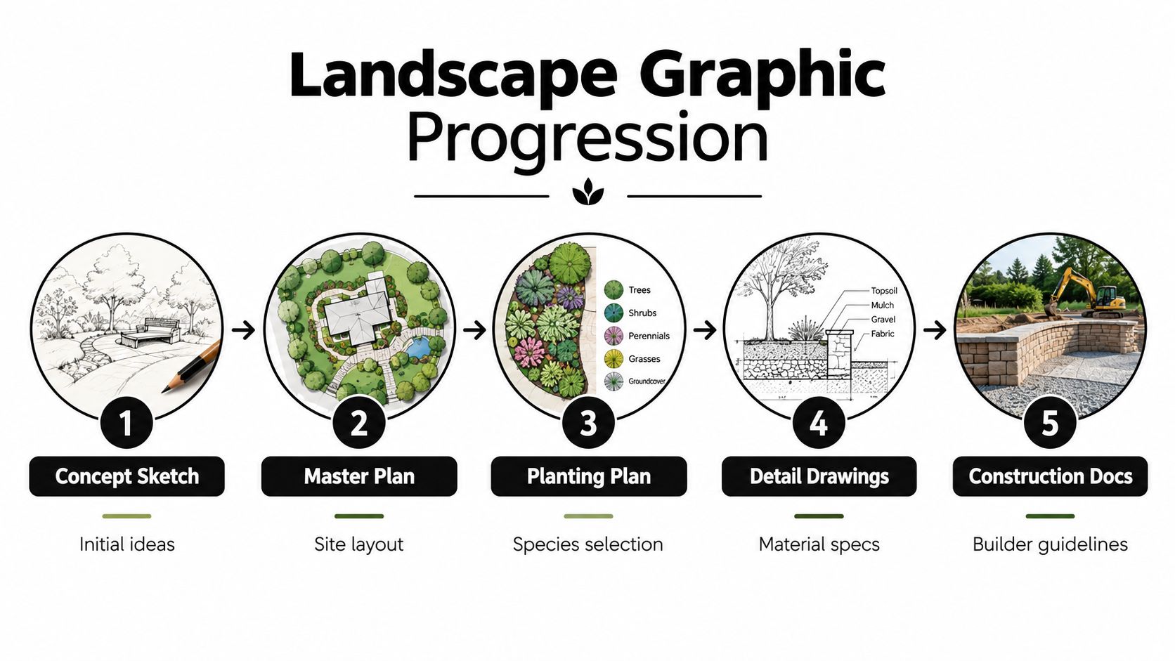
Sequence matters more than spectacle
A sensible sequence moves from broad decisions to controlled detail:
Concept sketch: tests routes, rooms, thresholds and views.
Masterplan: fixes the principal site arrangement.
Planting plan: develops species, structure, seasonal character and soil requirements.
Detail drawings: resolves materials, edges, levels and interfaces.
Construction documentation: gives the contractor coordinated information for delivery.
The stages don't operate in isolation. A planting decision can affect drainage. A basement stair can alter the garden's level strategy. An apparently simple terrace may require coordination with waterproofing, lighting and rainwater management.
The accompanying video provides another way to understand how garden ideas move from early communication towards resolved documentation.
Clients should ask what decision each graphic supports. If a drawing looks impressive but doesn't clarify ownership boundaries, levels, planting zones or construction interfaces, it may belong in a presentation rather than a planning or tender package.
British Standards and Planning Scales
Scale controls what a drawing can communicate. Choose a scale that's too small and planting beds, retaining edges and thresholds merge into unreadable marks. Choose one that's unnecessarily large and the drawing may lose the wider relationship between the garden, house, street and neighbouring properties.
UK planning conventions commonly use 1:50, 1:100, 1:200 and 1:500 for site design work, with larger context plans sometimes prepared at 1:1250, according to Cambridgeshire landscape guidance. Local authority guidance also commonly identifies location plans at 1:1250 for most sites, or 1:2500 for larger sites, and site or block plans at 1:200 or 1:500. These are not decorative conventions. They help reviewers compare drawings and understand the information appropriate to each level of detail.
A practical scale check
Use the drawing scale to match the decision being made:
1:50 is commonly suitable for a small domestic garden scheme or a highly detailed part of a garden.
1:100 can show a residential garden with useful clarity while retaining a coherent site view.
1:200 is often appropriate for a larger garden, house plot or coordinated outdoor proposal.
1:500 can communicate a wider site arrangement without pretending that every planting or junction is resolved.
1:1250 provides broader context, including surrounding streets and properties.
Every sheet should carry a north point, scale bar, drawing scale, clear key and boundary information. A scale bar remains valuable when a drawing is printed or viewed at a different size. A north point allows readers to understand orientation, sunlight and the relationship between buildings and outdoor spaces.
Planning application drawings also need consistent graphic conventions. Babergh guidance says landscaping schemes should use an accurate site survey, overlay the final development layout and use an adequate detailed scale such as 1:500, 1:200, 1:100 or 1:50, with a north point, scale bar and symbol key, as set out in its landscaping scheme checklist.
Symbols and boundaries
BS EN ISO 11091:1999 sets out general rules for site drawing practice, including graphical symbols and simplified representations for drawings. It provides a relevant professional reference because plans need to convey vegetation, surfaces and site elements without filling the sheet with prose.
Boundary lines also require discipline. Cheshire East guidance distinguishes the planning application area from land ownership, using a continuous red line for the application area and a continuous blue line for the owner's land, while separating existing and proposed features. These conventions help prevent a drawing from implying rights, works or ownership that the application doesn't cover.
Hard Versus Soft Landscaping Drawings
A garden has two overlapping systems. Hard landscaping provides the fixed framework, while soft landscaping introduces living material, soil and seasonal change. Drawing both on one attractive plan may seem efficient, but it can make the information harder to build and review.
A hard landscaping drawing should make the constructed components clear. That can include paths, patios, steps, retaining edges, walls, raised planters, water features, seating and hardstanding. It should communicate alignment, dimensions, levels, falls, materials and junctions with the building or garden structures.
A soft landscaping drawing deals with different questions. It identifies planting areas, relative vegetation heights, tree and shrub types, deep soil zones and irrigation points. It may sit alongside a planting schedule that records species, sizes, densities and maintenance expectations.
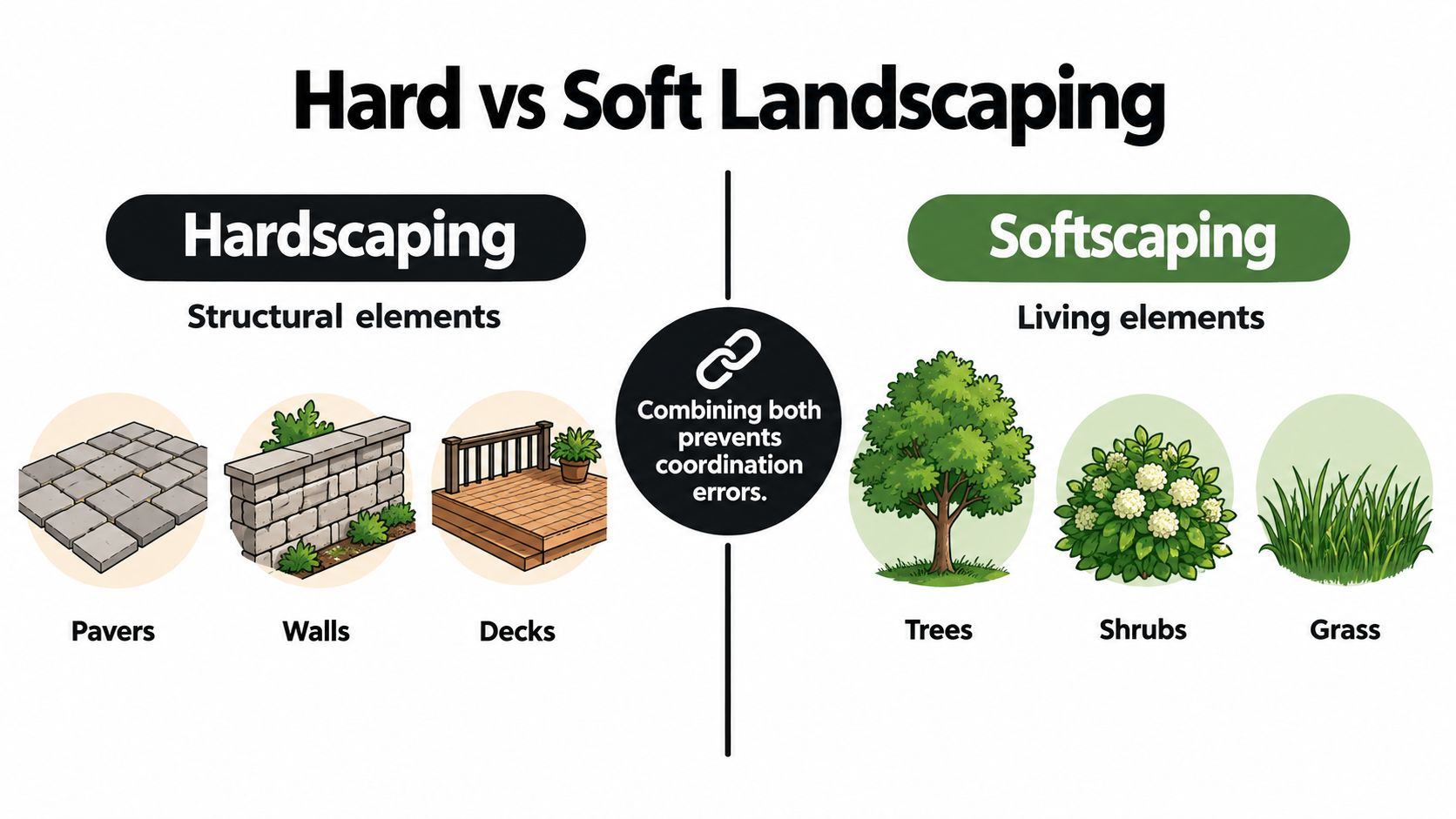
Why separation improves construction
Consider a basement-led refurbishment with a new terrace above part of the extension. The hardscape plan needs to coordinate the terrace build-up, thresholds, drainage falls, steps and waterproofing interfaces. The softscape plan needs to show where planting can establish, how much soil is available and how irrigation reaches the beds.
If these layers are merged without a clear hierarchy, several problems can follow:
Levels become ambiguous: a planting symbol may obscure a step, wall or finished-floor relationship.
Services disappear: irrigation, drainage and lighting routes can be lost beneath dense graphic information.
Planting is overpromised: a rendered canopy may suggest mature screening where the soil depth cannot support it.
Responsibility blurs: the builder, grounds contractor and engineer may interpret the same line differently.
Technical site information often uses 1:100, 1:200 or 1:500 for broader plans, with detailed sections or profiles tightened to 1:50 or 1:100 where soil depths, drainage falls and finished levels need precise reading, as described in this UK construction drawing guide.
Coordinate, don't isolate
Separation doesn't mean designing each layer independently. The hard plan should establish the geometry that the soft plan responds to. A tree shouldn't be placed over a drainage route without checking root space. A raised planter shouldn't be drawn without confirming its structure, waterproofing and soil volume.
The same principle applies to lighting. A landscape lighting design approach needs to coordinate fittings, cable routes, planting, steps and surfaces. The best drawing package keeps each information type readable while allowing the team to overlay and cross-check the layers.
Graphics for Luxury Residential Projects
A high-value house in South West London can combine a conservation area, a listed building, mature trees, a basement extension and several outdoor rooms. The graphics must make those constraints clear while showing a garden that still feels calm, private and usable.
Consider a Wimbledon Village project with a period house, a new basement leisure space and a garden falling away from the rear elevation. The brief includes a generous terrace, swimming pool, outdoor kitchen and garden room. Each element must fit the existing streetscape, protect neighbouring privacy and work with the site's levels.

The planning story sits beneath the image
A concept graphic can show the intended sequence of outdoor rooms, with the kitchen close to the house, the pool in a private part of the garden and the garden room framed by planting. It explains the design quickly, but it does not prove that the arrangement can be built. A levels plan checks whether the terraces, pool and access routes can be formed without an excessive change in ground profile. Sections then show retaining conditions, sightlines and the relationship between the basement, terrace and garden.
Heritage-sensitive work requires more than an attractive planting palette. Graphics should identify retained and removed trees, existing and proposed boundaries, visible structures, material changes and areas that contribute to local character. Where the impact matters to the planning decision, the authority may request accurate visual representations, streetscenes, cross-sections or shadow studies. Each drawing should answer a defined question, rather than repeat the same design in a different presentation style.
A persuasive plan doesn't make constraints disappear. It shows how the design responds to them.
A coordinated residential submission
Local authority requirements often sit across separate checklists, so homeowners may struggle to identify the drawings that carry planning weight. Horsham's landscape requirements indicate that a submission can include a masterplan, levels plan, hard and soft planting plans, and a coordinated utilities plan. It may also need a north point, scale bar, boundary lines, clear existing and proposed information, species schedules and, where relevant, sections or accurate visual representations.
For the Wimbledon project, the package could assign each document a specific purpose:
Masterplan: How do the principal garden spaces relate to the house and boundaries?
Levels plan: Can terraces, steps and the pool be built without harmful level changes?
Hardscape plan: Where are the paving, walls, stairs, pool and terrace elements located?
Softscape plan: Where will trees, shrubs, hedges and herbaceous planting establish?
Utilities plan: Can drainage, irrigation, lighting and other services be installed without compromising the design?
Sections and visual material: How will the proposal appear from relevant neighbouring or public viewpoints?
Domestic gardens may be exempt from a full management plan, while larger schemes may require one. The practical rule is clear: the drawing list should respond to the site and the planning risk, not to a generic presentation template. Attractive visuals establish intent. Statutory plans, schedules and sections provide the evidence needed to assess and deliver it.
Building a Cohesive Design Workflow
The strongest project packages don't treat site graphics as an administrative task added at the end. They use drawings to carry decisions from the first conversation through planning, technical coordination, procurement and site handover.
The process usually starts with the property, brief and constraints. A measured survey, arboricultural information, existing services, heritage context and the architectural proposal establish the facts. Early concept diagrams can then test movement, privacy, views, sunlight, outdoor rooms and the relationship between the garden and the house.
Let each stage answer a decision
At the masterplanning stage, the question is whether the arrangement works. The plan should make the principal geometry visible without pretending that every joint or plant has been selected. Once the arrangement is agreed, the levels strategy can test thresholds, stairs, retaining edges, basement connections and drainage.
Planting follows from those decisions rather than floating above them. Soil depth, shade, exposure, irrigation, maintenance and root space all influence what will thrive. A visually rich planting image may support the conversation, but the planting plan and schedule must record what the contractor is expected to source and install.
The technical package then brings the disciplines together:
Architect: coordinates building thresholds, walls, openings, materials and external rooms.
Designer: develops planting, surfaces, levels, furniture and garden character.
Engineer: checks structures, retaining conditions, drainage and service interfaces.
Contractor: tests buildability, sequencing, access and procurement.
Client: confirms priorities, appearance, maintenance expectations and budget decisions.
Review drawings before they reach site
A useful review checks more than spelling and line weights. Compare the site plans against architectural layouts, structural information, tree surveys, drainage proposals and utilities. Look for contradictions between the rendered image and the measurable drawings. Check that proposed features sit inside the correct application boundary and that existing and proposed elements are clearly distinguishable.
On site, the drawings should remain usable. A contractor needs to locate an edge, understand a level and identify a material without interpreting artistic intent. During handover, the record should explain what was installed, how planting is arranged and which elements need ongoing care.
Harper Latter Architects combines architectural and interior design for bespoke homes, including terraces, garden rooms and outdoor kitchens. For a project where the house, basement and garden need to work as one composition, Harper Latter Architects can help develop architecture plan graphics that connect design intent with planning and construction information. Visit the practice to discuss your property, constraints and the drawings your project is likely to require.

Comments